Lab 3 - Circuits
In this lab, we’ll get more familiar with combining the logic gates we experienced in class and the reading into more complicated circuits that can do multi-bit calculation. Rather than drawing these circuits on paper, we’ll use a digital logic designer app, Digital, to see them in action.
Lab Goals
After this lab, you should:
- Understand how to combine logic gates to produce multi-bit operations such as
- The ripple-carry adder
- Be able to picture how these circuits produce the results of our multi-bit operations
Getting Started
Installation
You need Java installed in your machine to be able to run Digital.
- If you are in or have taken DSA1, you likely already have Java installed!
- If not, we recommend following the instructions from Official Java documentation.
Download and run Digital
- View the Download instructions for Digital, an open source tool on GitHub, and download the zip file.
- Unzip the file and you should see a
Digital.jarfile in the extracted content. This is the entire app! - Run Digital
- You may be able to double click on the
Digital.jarfile and start the app. If that doesn’t work, - Open a Terminal (linux/mac) or Command Prompt/Powershell (windows),
cdinto the folder withDigital.jarand runjava -jar Digital.jarto start the app. - If you still have trouble, reach out to a TA.
- You may be able to double click on the
Important!
When you launch Digital for the first time, there is a short getting started guide that will walk you through the tool. PLEASE DON’T SKIP IT.
If you skipped the tutorial unintentionally, you can invoke it at View>Start Tutorial on the menu.
An Example in Digital
As a first example, let us examine the D Flip-flop circuit (i.e., the 1-bit register) we discussed in lecture. Don’t worry you are not expected to understand the internals of the D flip flop; use this example as chance to play with simulator to see how it works.
Download the demo .dig file above and open it in the Digital tool. To simulate your circuit, press the play button below the help on the menu bar. You can see the working of the D Flip flop by toggling the input (D) signal and observing the output (Q). The color of the input and output change to a brighter shade of green when the value is 1 (ON). You can right click on C to increase the clock frequency.
Testing circuits
We also have a testbench that tests the circuit’s functionality. To run the test bench, click on the play button with a green tick mark on it. The tool should run your circuit against the test cases and show you the input/output from the circuit.
Once you are done experimenting with the demo D Flip-flop, click on File>New to open a new diagram. This will clear the current example circuit and provide you with a blank workspace in which to create.
Digital
The tool provides all the logic gates we have discussed in the class so far, along with many other components. For the purpose of this lab, we will only be using the following, available under the Components menu:
- Logic (submenu)
- AND Gate (2)
- OR Gate (3)
- XOR Gate (4)
- Not Gate (1)
- IO (submenu)
- Input
- Output
- Plexers (submenu)
- Multiplexers
Note: For this lab, you should not need to use the NAND or NOR gates, but you are welcome to use them.
Practice drawing a few gates first. Review Digital’s built-in tutorial if you have not already.
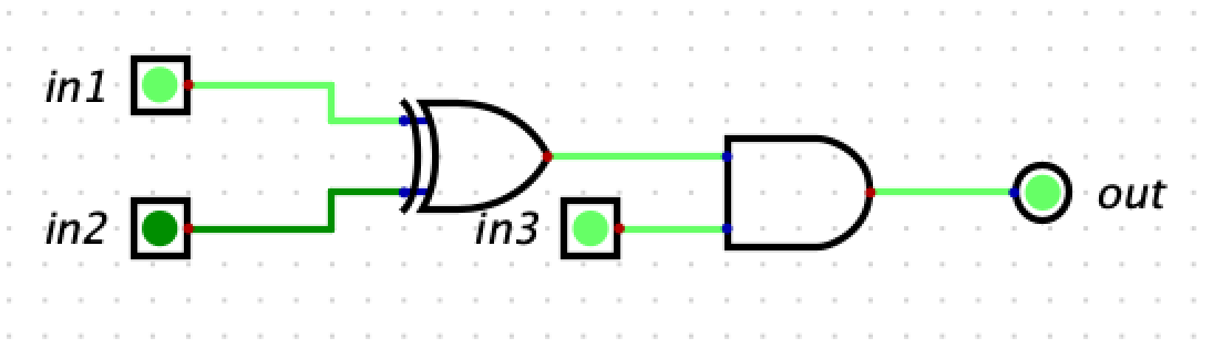
Below, we can see a simple circuit with 3 inputs and 1 output. The top two inputs (one 1 and one 0) are connected to an XOR gate. Since 1 ^ 0 = 1, we see that result is connected to the first input to the ADD gate. Our third input (1) is connected directly to the AND gate as its second input. Lastly, we see that the result of the AND is connected to an out put which reads H (or 1).
Example Circuit
Once you have become familiar with the simulator interface, it is time to try out some of our circuits from class.
Experimenting with Circuits
For the rest of lab, we’ll ask you to load, modify, or draw some circuits and then test them with a few inputs. The goal here is to understand more fully how the logic gates in our circuits combine to produce the answers we expect.
Ripple Carry Adder
Begin by loading the 4-bit Ripple Carry Adder that computes x = a + b, as discussed in the Fancier Logic reading and in class. Download ripple-carry-adder.dig, then open it in Digital. It should draw the ripple carry adder as seen below.
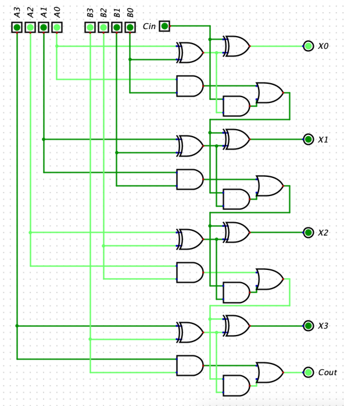
Ripple Carry Adder in Simulator adding 5 + 12 with overflow (or 5 + -4 in two’s complement)
We have collected the input wires in the upper left (4 bits for a and 4 bits for b), and the four output wires in the bottom right (4 bits for x). At the very bottom, you’ll notice the carry bit, which does not form part of the output for x. Clicking on an input bit’s value will change its value from 0 to 1 when the simulator is running.
Run the simulation and add the following numbers (given in decimal):
- 0 + 1
- 1 + 1
- 2 + 2
- 10 + 5
- 15 + 1
- 15 + 15
Note the output in each case and how any overflow is (or is not) handled in the circuit.
Now modify the adder to add 5-bit numbers instead.
Run the simulation again and add the following numbers (given in decimal):
- 0 + 1
- 15 + 1
- 16 + 15
- 31 + 1
- 31 + 31
Save your circuit by using the File, Save As menu and choosing a different filename. Do not share this with others outside your lab group, but save a copy to check off with your TA.
Towards a Computer
Next we will create a new circuit.
In class, we have been working towards building a computer that we can program with instructions. We created circuits to handle the work, but we will want to add a mux so that the computer can choose which resulting value should be stored in which register for the next calculation.
For the rest of lab today, we will build a simplified version to visualize how the circuits will work. In this simplified version, we will define 4-bit instructions [CCAB] as follows:
- The first two bits (
CC) will be the instruction code (that is, the “icode”) that determines what operation we will compute - The third (
A) and fourth (B) bits will be the two input values1
Our simplified circuit will compute a specific operation, depending on which icode is provided in the input, and will output its result as follows:
| icode | operation |
|---|---|
0 | NOT a |
1 | a AND b |
2 | a OR b |
3 | a XOR b |
In our circuit, these 4-bit instructions enter as 4 separate 1-bit inputs, just as the inputs for x and y did in the ripple carry adder above. For example, if our instruction was 0110, the icode bits are 01 and the operands are 1 and 0; therefore, our circuit would output the result of 1 AND 0, which is 01. We will build this circuit in 2 parts: one part that handles the icode and another that handles the calculations.
Handling the icodes
To choose which operation’s value to output, we will use a multiplexer (mux). Note that we have 4 icode values, so we must construct a 4-input mux, which requires a 2-bit choice value. Build this mux on the right-hand side of the simulator window. You can select a 1-bit (2-input) multiplexer from the Plexers submenu in the Components menu. You may not use the built-in Digital 2-bit mux.
Once completed, you should have 4 wires ready for inputs to be connected to your new 4-input mux, the final Logic Output connected to the output of your mux, and the first two Logic Inputs of our instruction (the first two input bits) used as the choice.
Performing the operations
Next, we must calculate the operations. We will always calculate all 4 operations; our mux will determine which operation is ultimately output2.
- Draw gates for each of the 4 operations, connecting their output to the respective input of the 4-input mux.
- Draw 2 Logic Inputs that will serve as the last two bits of our 4-bit instruction. Connect them to each logic gate in the previous step, as appropriate.
Testing your circuit
Once you have completed your circuit, try out a few different instructions:
0001- This should NOT 0 (outputting 1)0011- This should NOT 1 (outputting 0)0110- This should AND 1 and 0 (outputting 0)0111- This should AND 1 and 1 (outputting 1)1011- This should OR 1 and 1 (outputting 1)1010- This should OR 1 and 0 (outputting 1)1111- This should XOR 1 and 1 (outputting 0)
Save your circuit by using the File, Save As menu. Do not share this with others outside your lab group, but save a copy to check off with your TA.
Check-off with a TA
To check-off this lab, show a TA
- Your 5-bit ripple carry adder displaying the result of
28 + 3 - Your multi-purpose circuit with the instructions
1010,1110, and0100
-
Note: this is different from our instructions in class to make designing the circuit in the simulator easier. In class, the two operands will tell us from which register to read (or write) the value. ↩ ↩2
-
In class, this output would be routed to the register file to be saved as needed and used in a future calculation. In our simplified circuit, we are not asking you to draw the register. If you wanted to experiment with it after class, the 1-bit D flip-flop register shown in class is available in the Components->->Flip-Flops menu as the D Flip-Flop. ↩